Lab 1: FPGA and MCU Setup and Testing
Introduction
In this lab, a FPGA design was implemented to 1) blink an LED at 2.4Hz using an on-board high-speed oscillator, 2) control 2 LEDs with 4 switches, and 3) display a 4-digit binary input in hexadecimal using a 7-segment display. The logic of the second function, controlling LEDs with switches, is shown below:
| s[3:2] | LED[1] | s[1:0] | LED[0] |
|---|---|---|---|
| 00 | 0 | 00 | 0 |
| 01 | 1 | 01 | 0 |
| 10 | 1 | 10 | 0 |
| 11 | 0 | 11 | 1 |
Design
The top level design, lab1_gt, included three modules: the on-board high-speed oscillator (HSOSC) from the iCE40 UltraPlus primitive library, a counter for the blinking LED, and a 7-segment display decoder. The general idea of the design can be visualized with the block diagram below:
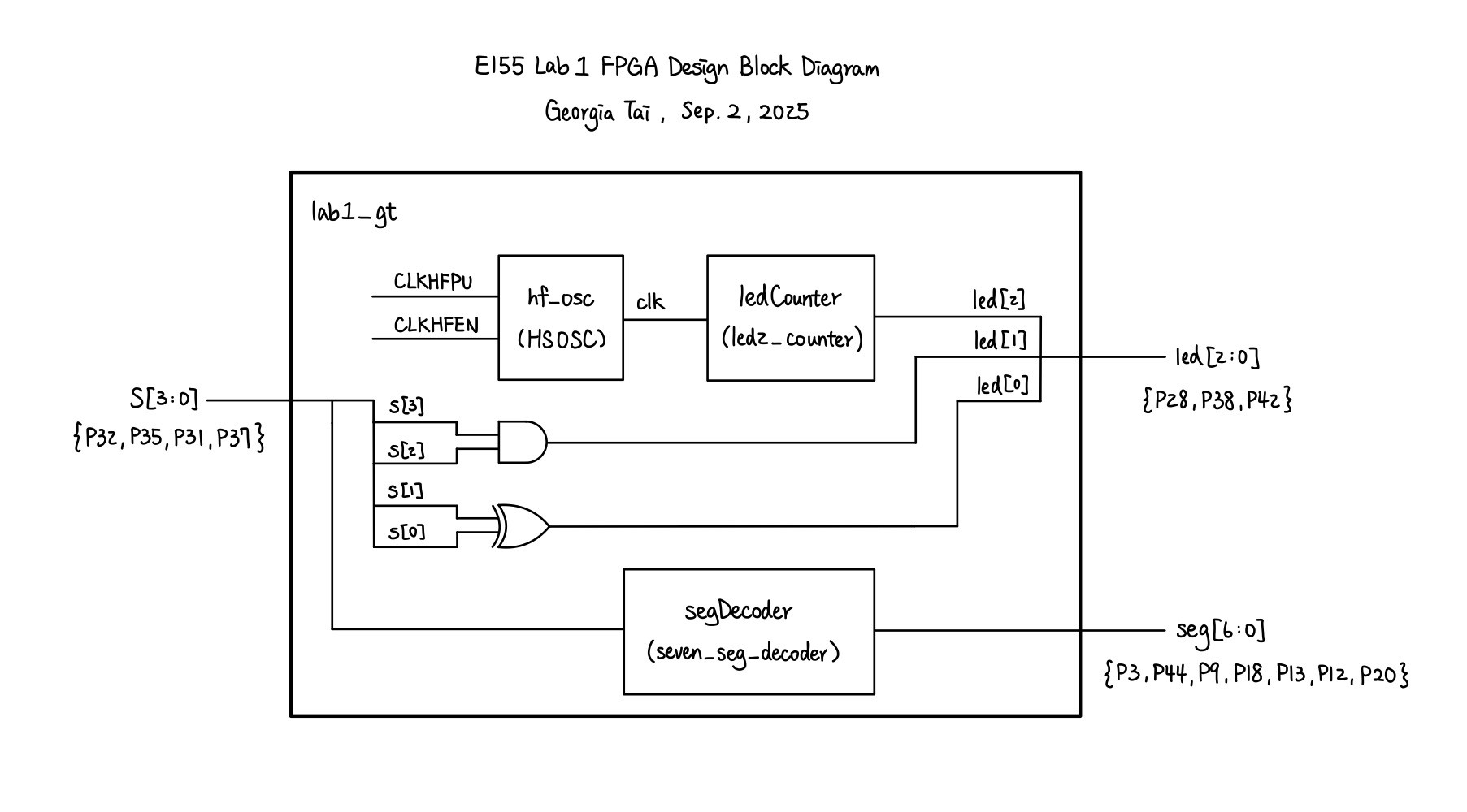
The 7-segment display decoder simply contained a set of combinational logic to translate a 4-bit binary signal into a single hexadecimal value. Each segment of the display is a LED controlled by an I/O pin from the UPduino board, and the shape of each hexadecimal value is unique, which will later be demonstrated in the Results section of this page.
The LED decoder included combinational logic to assign led[0] and led[1] using the inputs switches[3:0]. According to Table 1, led[1] can simply be assigned through a XOR gate and led[0] through an AND gate. The module also takes in a 24 MHz clock input clk given by the high-speed oscillator. It then uses a counter incremented at each clock cycle to toggle led[2] every 5 million cycles, allowing the LED to blink at 2.4 Hz.
On the physical side of design, the 7-segment display was externally accessed on a breadboard. The switch used for inputs and the LEDs are soldered on the board provided by the course. The schematics for the physical circuit design is shown in the following graph:
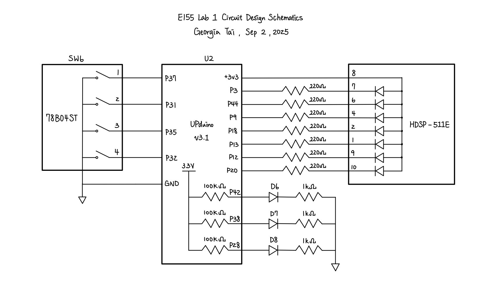
A resistor value of \(220 \Omega\) are chosen considering the voltage and current across the LEDs. According to the 7-segment display datasheet, the ideal current across the LEDs on the display should be 20mA. Given that \(V = IR\), a driving voltage of \(3.3V\) and a voltage drop of \(2.1V\) across red LEDs,
\[ R = \frac{3.3V - 2.1V}{0.02A} = 60 \Omega \]
Since \(220 \Omega > 60 \Omega\), a \(220 \Omega\) resistor would allow the current to stay within the safety range and was tested to provide enough brightness.
Testing and Results
At the beginning of the lab, we first had to solder the components onto the board. After soldering the board, I tested it with the Radiant tutorial provided on the course website and verified that the componenets are working as expected.
The led2_counter module, which is used to make one of the LEDs blink at 2.4 Hz, is hard to test through a testbench due to its use of high-frequency oscillators. Alternatively, we can directly verify its functionality using an oscilloscope to measure the frequency of the blinking LED. As shown in Figure 3, led[2] is indeed blinking at approximately 2.4 Hz, fitting the one of the requirements of the lab.
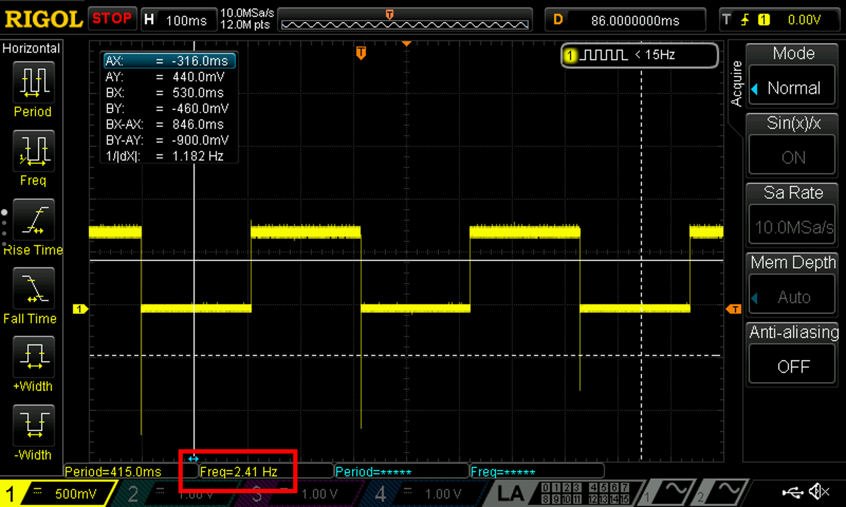
led[2]
Since the inputs were only four switches, or 16 combinations, the other two self-designed modules, lab1_gt and seven_seg_decoder, can be easily tested through automated testbenches. I wrote two testbenches, one for the top level module and the other for the seven segment display decoder, then created TV-file test vectors accordingly. Using Questa to simulate, the following figures show that both modules have successfully passed their testbench. Note that the led[2] is previously tested and can be neglected here.
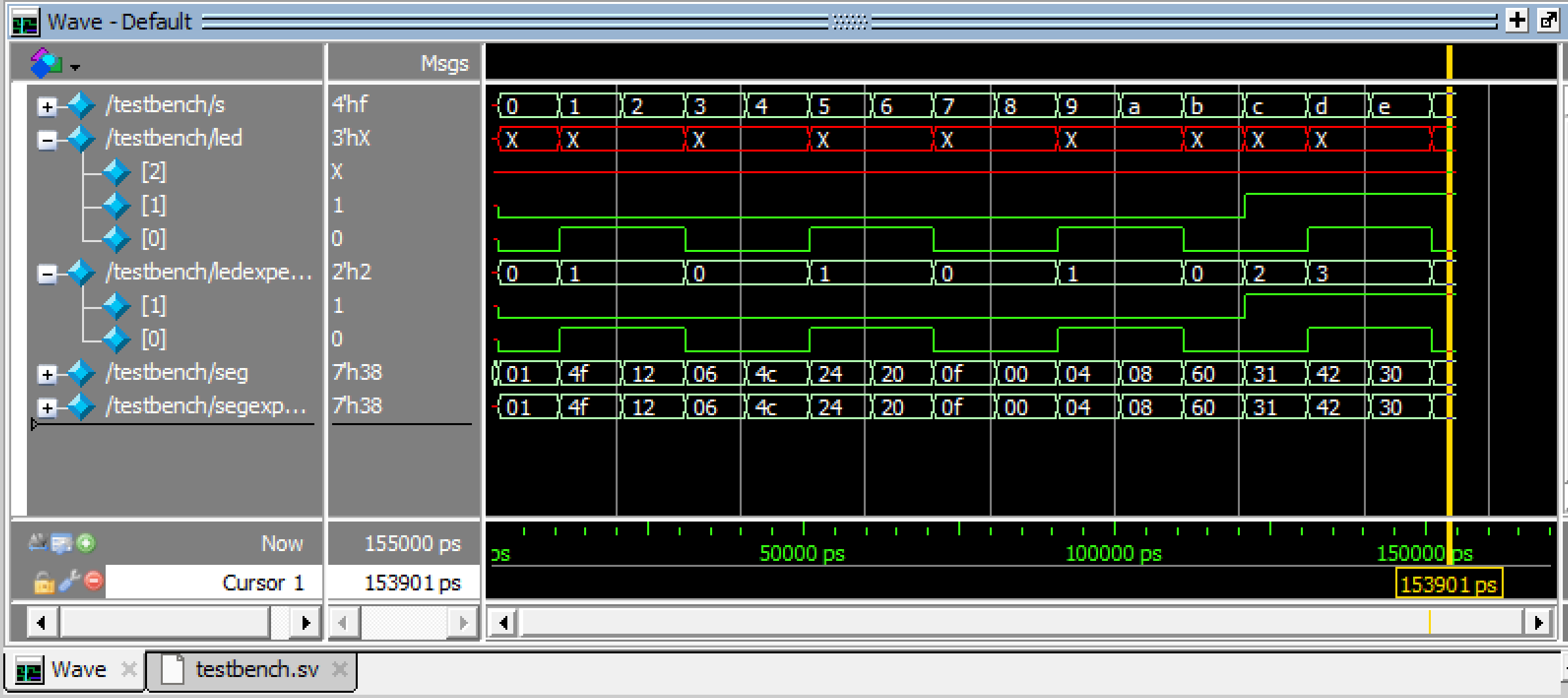
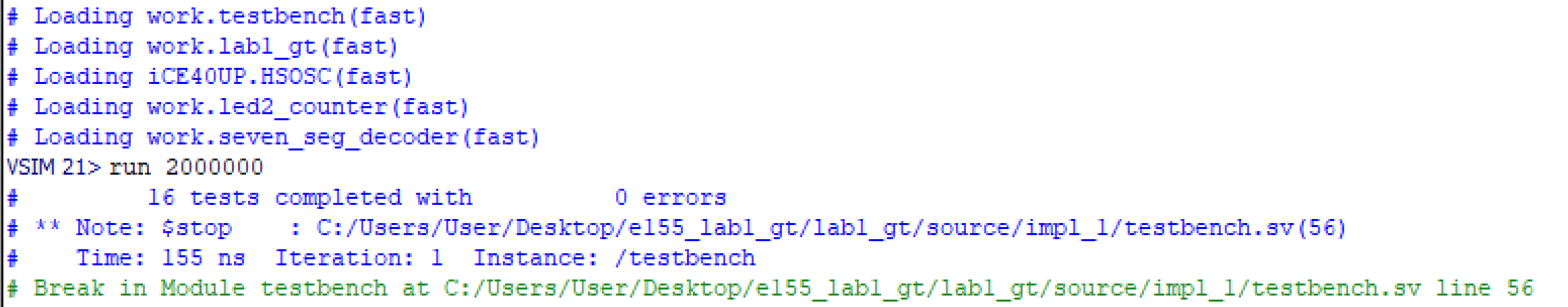
lab1_gt
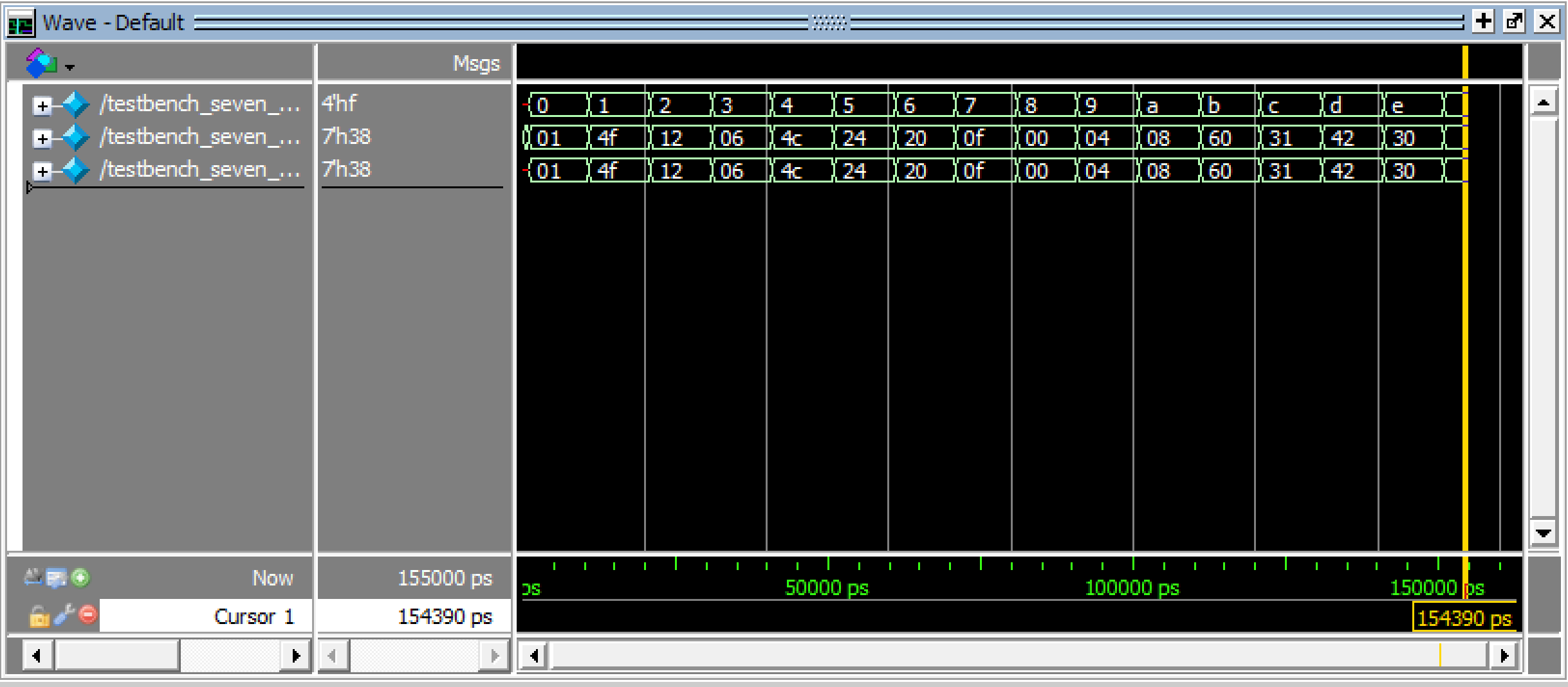
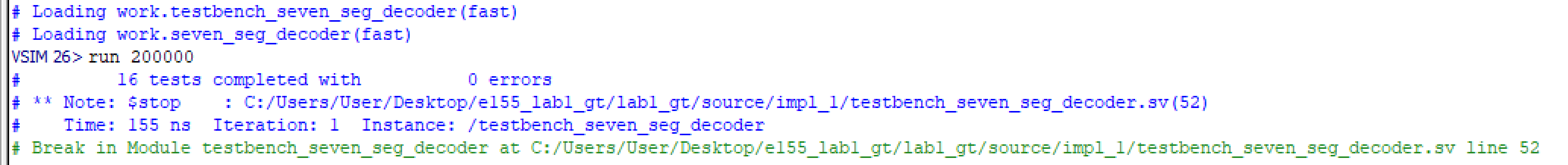
seven_seg_decoder
After verifying the code with testbenches, the circuit which I built also has to be tested. The following video shows a completely demo of me trying all 16 combination of switch inputs on my system. As shown in the video, each combination of switches, relating to a single hexadecimal digit, has a unique pattern and was able to turn on successfully. On top of that, the three LEDs close to the left-bottom corner of the ribbon cable performed as expected. The two non-blinking LEDs, with the right one being led[0], worked according to the described logic of led[1] and led[0]. Although this video was sped up by 1.5 times, the blinking LED led[2] was blinking at the expected frequency of 2.4 Hz, as previously verified.
Conclusion
In this lab, I successfully designed and built a seven-segment display, which was able to translate a 4-bit input given by a set of switches into unique single digit hexadecimal number. I was also able to create the LEDs as the lab required. Therefore, I believe that my design for this lab meets all the requirements of this lab. This week, I spent 15 hours on the lab. A lot of time was put into installing things and getting familiarized with the apps and environment. Hopefully, the whole lab flow would be easier in the future, and I can work more efficiently, focusing on designing and verifying the systems.
AI Prototype Summary
For the AI prototype, I chose to use the default model of ChatGPT. After putting in the promopt, it returned its first code which had this error and caused systhesis to fail:
ERROR <35901063> - c:/users/user/desktop/e155_lab1/fpga/radiant_project/ai/source/impl_1/top.sv(17): instantiating unknown module SB_HFOSC. VERI-1063 [top.sv:17]Looking at this error, I noticed that it was using a different module name compared to what we used, HSOSC, but I wasn’t sure if this module specified by chatGPT was actually available. However, I decided to simply throw in the error. ChatGPT insisted that SB_HFOSC was the right module, and repeatedly asked me to check my settings. At some point, it even threw in the idea of declaring the module as a black box with (* blackbox *), whicih also caused other trivial issues and was still unable to solve the root cause. Knowing that this is a rabbit hole, I decided to search up SB_HFOSC online and found the following information in the iCE40 Oscillator Usage Guide:
1.1. Key Features The following oscillators are available to iCEcube2 users: SB_LFOSC – Low Frequency Oscillator, SB_HFOSC – High Frequency Oscillator with output divider The following oscillators are available to Lattice Radiant Software users: LSOSC – Low Frequency Oscillator, HSOSC – High Frequency Oscillator with output divider
I gave this information back to ChatGPT, and it then returned another draft of the module, which passed systhesis this time.
Overall, I would rate the experience for coding with ChatGPT a 5.5/10. It did help explaining the calculations and also drafting the code, but I feel never really felt confident in the things it produced and had to also do a self mental check. Personally, I feel more confident in debugging and finding the non-reasonable parts from a piece of code than writing one from scratch. In this case, for example, I was able to find the unfamiliar module from ChatGPT’s code and also think of ways to make the code cleaner, but that was also partially because I had prior knowledge to the prompt. This time, ChatGPT providing a somewhat feasible draft did help improve the work efficiency, thus I rated it an above average score. That being said, the quality of it’s code is not always consistent, and I would most likely suggest one to be fairly confident in the topic of the prompt before asking a LLM to code from scratch.