Lab 4: Digital Audio
Introduction
The goal of this design is to practice using the MCU by generating square waves with timers and toggling a GPIO pin at specific frequencies and durations to play music.
Design
For this lab, I used libraries provided by the course for setting up the RCC, FLASH, and GPIO. Then, I referenced the STM32L432KC reference manual, programming manual, and datasheet. This helped creating code for setting up TIM15 and TIM16, which are general purpose timers used here for waiting a certain duration and generating the PWM signal, respectively.
The two timers are similar enough such that they are defined with a single struct and kept in the same header file, STM32L432KC_TIM.h. The file STM32L432KC_TIM.c contains functions with initializing the two timers and also functions for their waiting and signal generating purpose. TIM15 was initialized according to the manuals with initTIM and waits for ms milliseconds with the function delay_millis. TIM16 was initialized with function initPWM and uses the function PWM_setDutyCycle to generate a PWM signal with a certain duty cycle and frequency. Its output is sent from TIM16_CH1 to PA6 in GPIOA of the MCU.
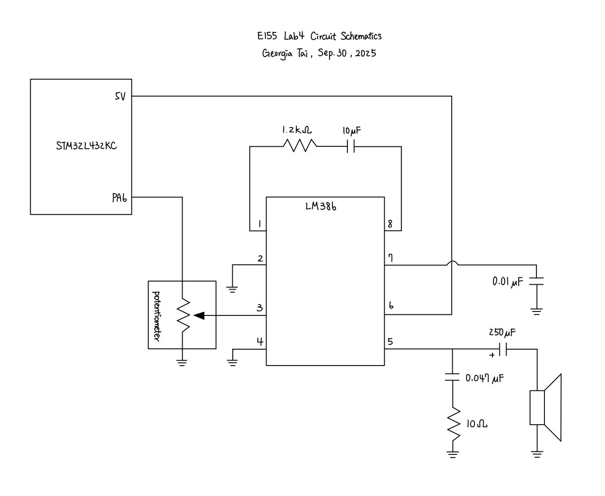
The circuitry design was referenced from the LM386 datasheet, where I chose to use the circuit with a gain of 50. The schematics for the physical circuit design is shown in the following graph:
Prescalar Value Calculations
The formula for the ARR, the auto-reload value, or the number of cycles compared with the count, can be calculated by the following formulas. The ARR field in the registers has 16 bits. Therefore, \(0 \leq ARR \leq 2^{16}-1=65535\). The ARR value for duration can simply be calculated by the wait time multiplied by the frequency of the timer. Note that the wait time is inputted with an unit of milliseconds, and is thus scaled to seconds to comply with the timer frequency. Choosing a prescalar value of 4999 for the counter: \[
ARR_{cnt} = \frac{t}{1000} \times f_{TIM} = \frac{t}{1000} \times \frac{f_{clk}}{(PSC_{cnt} + 1)}
\]
The minimum duration is found when ARR has the smallest value possible, or \(ARR=0\): \[
ARR_{cnt, min} = \frac{t_{min}}{1000} \times \frac{80000000}{4999+1} = 0 \Rightarrow t_{min} = 0 \ ms
\]
The maximum duration is found when ARR has the largest value possible, or \(ARR=65535\): \[
ARR_{cnt, max} = \frac{t_{max}}{1000} \times \frac{80000000}{4999+1} = 65535 \Rightarrow t_{max} = 4095.9375 \ ms
\]
Therefore, the duration which the system can take is from 0 to approximately 4096 ms. On the other hand, the maximum and minimum frequency which the device can play is calculated with the following equation, with a chosen prescalar value of 799: \[ f_{note} = \frac{f_{TIM}}{ARR+1} = \frac{f_{clk}}{PSC_{PWM}+1} \times \frac{1}{ARR+1} \] \[ \Rightarrow ARR_{PWM} = \frac{f_{clk}}{PSC_{PWM}+1} \times \frac{1}{f_{note}} - 1 \]
The minimum frequency is found when ARR has the largest value possible, or \(ARR=65535\): \[
ARR_{PWM, max} = \frac{80000000}{799+1} \times \frac{1}{f_{note, min}} - 1 = 65535 \Rightarrow f_{note, min} \approx 1.526 \ Hz
\]
The maximum frequency is found when ARR has the smallest value possible, or \(ARR=0\): \[
ARR_{PWM, min} = \frac{80000000}{799+1} \times \frac{1}{f_{note, max}} - 1 = 0 \Rightarrow f_{note, min} = 100000 \ Hz
\]
Therefore, the frequency which the system supports is from approximately 1.526 to 100000 Hz.
For the frequency range of 220 to 1000 Hz, which is commonly used for most music, we calculate the error of our device from the desired frequency. We also choose 600 Hz to better represent across the range. First, we can calculate the actual ARR value with our chosen PWM timer prescalar of 799, note that the number is treated as int and rounded to the nearest whole number: \[
ARR_{PWM, 220Hz} = \frac{80000000}{799+1} \times \frac{1}{220} - 1 \approx 453.54 \approx 454
\] \[
ARR_{PWM, 600Hz} = \frac{80000000}{799+1} \times \frac{1}{600} - 1 \approx 165.67 \approx 166 \\
\] \[
ARR_{PWM, 1000Hz} = \frac{80000000}{799+1} \times \frac{1}{1000} - 1 = 99
\]
The real PWM frequency produced by this ARR value is thus: \[
f_{220Hz, prod} = \frac{80000000}{799+1} \times \frac{1}{ARR_{PWM, 220Hz} + 1} \approx 219.780219
\] \[
f_{600Hz, prod} = \frac{80000000}{799+1} \times \frac{1}{ARR_{PWM, 600Hz} + 1} \approx 598.8024
\] \[
f_{1000Hz, prod} = \frac{80000000}{799+1} \times \frac{1}{ARR_{PWM, 1000Hz} + 1} = 1000
\]
The error for each of these frequencies is: \[ err_{220Hz} = \frac{f_{220Hz, prod} - 220}{220} \approx -0.000999 \approx -0.1\% \] \[ err_{600Hz} = \frac{f_{600Hz, prod} - 600}{600} \approx -0.001996 \approx -0.2\% \] \[ err_{1000Hz} = \frac{f_{1000Hz, prod} - 1000}{1000} = 0 \]
The error for each frequencies is well below 1%, we can thus assume that the error will also be below 1% across the frequency range of 220 to 1000 Hz on the device.
Testing and Results
I was able to play Für Elise with the correct pitch and durations. On top of that, I chose to transcribe and another song of my choice: Cheat Code by NCT WISH. Since I couldn’t find any free scores available online, I decided to simply listen and transcribe the last chorus of the song into a score, then making it into a series of pitches and durations. My device can successfully play the song, but it also made me realize how much more lively the song was with the arrangements. If I had more time, I think I would want to try recreating such arrangements, perhaps through changing pitches really rapidly, similar to some techniques that beat-boxers would use.
Conclusion
In this lab, I successfully designed and built a MCU design that was able to play songs with correct pitches and durations, including the rests. As shown in previous sections, the pitches are calculated to be accurate within 1% across the frequency range. Therefore, I believe that my design for this lab meets all the requirements of this lab. This week, I spent 10 hours on the lab. Most of my times were spent on understanding the manuals and how each registers collaborated with each other. I hope I will be even more familiar with this process within the next few labs.
AI Prototype Summary
For this AI prototype, I used ChatGPT. When feeding it the first prompt, it concluded that:
On the Nucleo-L432KC, TIM2 is especially convenient because it’s 32-bit and widely mapped to GPIO pins. But for your frequency range, a 16-bit timer (like TIM15/16/17) is more than enough.
It provided the formula to the correct timer frequency, however, the output frequency was different from what I expected by a factor of 2, as I believe that it was confusing the frequency with the duty cycle and the actual frequency of the note. For setting up the timers, it first suggested setting up RCC without much instructions, then PSC, ARR, CCRx, CCMRx, CCER, BDTR, GPIO_AFR, and CR1. The list pretty much covers what I have for making my device to work, but did not include EGR to update the events.
After providing the reference manual and asking ChatGPT to confirm/modify its previous answer, it detailed the answer better, providing more keywords found in the manual, such as TIM2_CHx for the output channel of the timers, and explained better the mapping between the GPIO and the timers. It did not change anything about the formula, but did additionally mention EGR for as an optional step when setting up the timers.